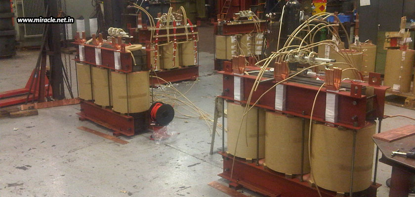
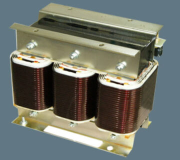
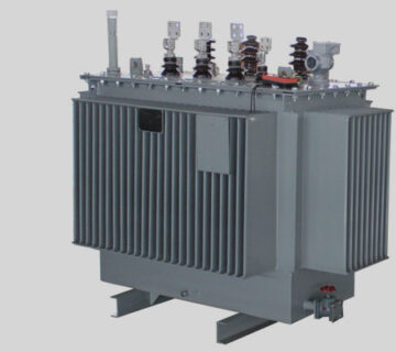
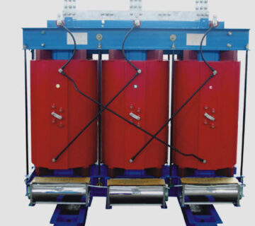
Transformers are static electrical devices that transfer AC electric power from one circuit to another at a constant frequency, while increasing or decreasing the voltage, as required by the equipment. The process that helps such transfer is electromagnetic induction.
When a winding supplied by an AC source produces a continually changing and alternating flux surrounding the wounding, and another winding is brought in close proximity, some part of the alternating flux will link with the second winding. Such change in flux results in changing flux linkage in the second winding. There will be an EMF induced in the second winding, as a result.
Different types of windings used in a transformer
As you can see, windings play a very important role in the working of a transformer. With different transformer types, there are different types of windings used.
Cylindrical windings – Multi layered windings
These are windings with low voltage that use up to 6.6 kV for kVA up to 600-750, and have a current rating between 10 and 600 A. these are mostly used in multi-layered forms with circular conductors, wound on vertical strips to improve the cooling conditions. The maximum diameter of a bare conductor used for this type of windings is 4mm.
Helical windings – Single, double, multi layered, and disc helical windings
These windings are used for low voltage and high capacity transformers, where the current is higher and the winding turns are lesser. In this case, the output of the transformers varies from 0.23 to 15 kV for 160 to 1000 kVA. The cross-sectional area of the strip is made not less than 75-100 mm square, in order to secure the adequate mechanical strength; and the maximum number of strips used to make up the conductor in parallel is 16.
Single Helical Windings – The windings in axial direction along a screw line with inclination are known as single helical windings, which consist of only one layer of turns in each winding.
Double Helical Windings – The reduced number of parallel conductors in a radial direction reduce the eddy current loss in conductors.
Disc Helical Windings – The parallel connected strips are placed side to side in a radial direction to occupy total radial depth of the winding.
Multi-layer Helical Windings – Several cylindrical layers are concentrical, and wound and connected in series. These windings are used for high voltage ratings like 110 kV and above. The outer layers are shorter than the inner layers, so as to distribute the capacitance uniformly.
Cross-over windings
Used for high voltage windings of small transformers, the conductors are paper-covered strips or round wires. They help to reduce voltage between adjacent layers, as they are divided into multiple coils, separated by a distance of 0.5-1 mm, with voltages between adjacent coils being more than 800-1000 V. The axial length and width of each coil are around 50 mm and 25-50 mm respectively, with the spacing between two coils being 6 mm.
Disc and continuous disc windings
They are used for high capacity transformers, wherein the windings consist of numerous flat coils in a series or parallel formation. The coils are formed with the help of rectangular strips wound spirally from the center outwards in a radial direction. The conductors can be single or multiple strips in parallel formation wound on the flat side. The discs are separated from one another with the help of press-board sectors attached to vertical strips. The area of the conductor ranges between 4 to 50 mm square, with current ranging from 12 to 600 A.
Now that you know about all the various kinds of windings used in different types of transformers, you should be in a better position to have your transformers customized. And for this, you can get in touch with a reliable transformer manufacturer in Germany, one like Miracle Electronics.


